Home › Unlabelled ›
Reading Electrical Schematics Drawings - Draw Wiring Diagrams Page 1 Line 17qq Com - There are other equally important types of drawings that are not the subject of this article including logic diagrams, data tables and single line diagrams, wiring diagrams, data communication.
Reading Electrical Schematics Drawings - Draw Wiring Diagrams Page 1 Line 17qq Com - There are other equally important types of drawings that are not the subject of this article including logic diagrams, data tables and single line diagrams, wiring diagrams, data communication.. One of the first steps in reading an electrical schematic is understanding the different symbols used to represent system components, or at least having access to a schematic symbol. The reason for this is to make the drawing simpler. Trace through sequence of operation using ladder diagrams: Each physical component (i.e resistor, capacitor, transistor) has a unique schematic symbol. To learn to read the electrical schematic you also have to know about the different symbols that is used in electrical schematics such as the symbols of resistors online tutorial and by working with engineers and the kit the drawing represents, also have a go at designing simple control panels.
To learn to read the electrical schematic you also have to know about the different symbols that is used in electrical schematics such as the symbols of resistors online tutorial and by working with engineers and the kit the drawing represents, also have a go at designing simple control panels. Electrical schematic diagrams single line diagrams p&id diagrams panel layouts. An electrical schematic is a logical representation of the physical connections and layout of an electric a title block is the border and text of the drawing that describes the project and current sheet. This tutorial should turn you into a fully literate schematic reader! There are other equally important types of drawings that are not the subject of this article including logic diagrams, data tables and single line diagrams, wiring diagrams, data communication.
New Wiring Diagram For Ge Electric Motor Diagram Diagramsample Diagramtemplate Wiringdiagram Diagramchart Worksheet Diagram Schematic Drawing Dryer Plug from i.pinimg.com Electrical symbols and electronic circuit symbols are used for drawing schematic diagram. This includes ac schematics and dc schematics and diagrams that prominently feature relaying. The flow of the power or main signal is. A circuit diagram (electrical diagram, elementary diagram, electronic schematic) is a graphical representation of an electrical circuit. Trace through sequence of operation using ladder diagrams: Schematic charts are blueprints that help you or a technical professional understand the electrical circuitry of a specific area. Crash course on how to read electrical schematics. Start drawing lines by clicking on the draw lines tool in the smartpanel.
Each physical component (i.e resistor, capacitor, transistor) has a unique schematic symbol.
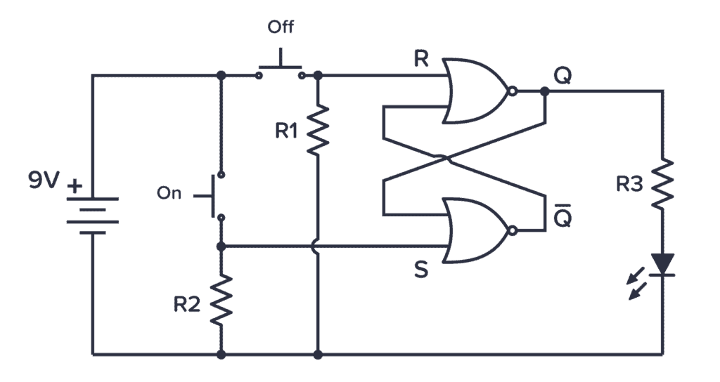
Circuit drawing or electronic schematic drawing is not a hard to learn stuff, you can make it better with practice. To learn to read the electrical schematic you also have to know about the different symbols that is used in electrical schematics such as the symbols of resistors online tutorial and by working with engineers and the kit the drawing represents, also have a go at designing simple control panels. On a schematic you will also see a electrical components symbol next to it will have a identification number next to its abbreviation (ie. An electronic schematic is a diagram that uses standardized electronic and electrical symbols to generally, schematics are laid out to read like text in a book. Well there are some standard practices that you have to keep in mind while you draw. A circuit diagram (electrical diagram, elementary diagram, electronic schematic) is a graphical representation of an electrical circuit. To start developing your schematic reading abilities, it's important to memorize the most common schematic symbols. Trace through sequence of operation using ladder diagrams: The flow of the power or main signal is. A schematic you find on the internet sometimes includes only electronic components and no connectors. .will talk about how to read a schematic and how to identify electrical components on a pcb (printed circuit board).electrical components are identified two main ways. We will write an article regarding the standard practices to follow while drawing circuit diagrams. Read schematics in the pattern that you would read the text.
Electrical plans are primarily diagrammatic. Circuit drawing or electronic schematic drawing is not a hard to learn stuff, you can make it better with practice. What are blueprints and schematic diagrams for electrician? Potential sheet to sheet cross referencing. While schematics require some basic knowledge of electrical hardware, you can gain a lot of new insights into your home or property by.
Schematic Symbols The Essential Symbols You Should Know from www.build-electronic-circuits.com To learn to read the electrical schematic you also have to know about the different symbols that is used in electrical schematics such as the symbols of resistors online tutorial and by working with engineers and the kit the drawing represents, also have a go at designing simple control panels. While schematics require some basic knowledge of electrical hardware, you can gain a lot of new insights into your home or property by. Well there are some standard practices that you have to keep in mind while you draw. However, electrical drawings contain a complex set of symbols and interconnection notation that can be difficult to. To read and interpret electrical diagrams and schematics, the basic symbols and conventions used in the drawing must be understood. By default, you'll draw a segmented line with an arrow at one end. Schematics produced in a professional cad package. With rare exceptions, schematics should be read left to right.
Electrical symbols and electronic circuit symbols are used for drawing schematic diagram.
What are blueprints and schematic diagrams for electrician? Electrical plans are primarily diagrammatic. Understanding schematic drawings helps identify faulty components, troubleshoot systems, and improve safety. An electronic schematic is a diagram that uses standardized electronic and electrical symbols to generally, schematics are laid out to read like text in a book. Well there are some standard practices that you have to keep in mind while you draw. Crash course on how to read electrical schematics. 6 electrical drawings and schematics drawings showing key plan and plan/layout of buildings, facilities and services most plants are large enough that scale drawings also allow components and systems that are too large to be drawn full size to be drawn in a more convenient and easy to read size. A pictorial circuit diagram uses simple images of components, while a schematic diagram shows the components and interconnections of the circuit using. The reason for this is to make the drawing simpler. A schematic you find on the internet sometimes includes only electronic components and no connectors. Electrical symbols & electronic symbols. One of the first steps in reading an electrical schematic is understanding the different symbols used to represent system components, or at least having access to a schematic symbol. Once you know how to read an electrical schematic, the next step is to design your own.
.will talk about how to read a schematic and how to identify electrical components on a pcb (printed circuit board).electrical components are identified two main ways. Electrical plans are primarily diagrammatic. We will write an article regarding the standard practices to follow while drawing circuit diagrams. Electrical symbols & electronic symbols. This tutorial should turn you into a fully literate schematic reader!
Wiring Diagrams Petroed from www.petroed.com A schematic you find on the internet sometimes includes only electronic components and no connectors. Electrical plans are primarily diagrammatic. To read and interpret electrical diagrams and schematics, the basic symbols and conventions used in the drawing must be understood. Reading schematics is just a matter of recognizing the symbols and see how they connect. Schematic comprehension is a pretty basic electronics skill, but there are a few things you should know before you read this tutorial. Electrical basics sample drawing index. Once you know how to read an electrical schematic, the next step is to design your own. An electrical schematic is a logical representation of the physical connections and layout of an electric a title block is the border and text of the drawing that describes the project and current sheet.
A schematic you find on the internet sometimes includes only electronic components and no connectors.
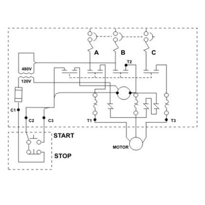
Anyone who wants to install, maintain, or repair electrical systems relies on drawings to understand the layout of components and create new distribution systems and circuits. While schematics require some basic knowledge of electrical hardware, you can gain a lot of new insights into your home or property by. This tutorial should turn you into a fully literate schematic reader! What are blueprints and schematic diagrams for electrician? Electrical symbols and electronic circuit symbols are used for drawing schematic diagram. A ladder schematic is a drawing intended for tracing specific circuits. Understanding how to read and follow schematics is an important skill for any electronics engineer. However, electrical drawings contain a complex set of symbols and interconnection notation that can be difficult to. Circuit drawing or electronic schematic drawing is not a hard to learn stuff, you can make it better with practice. Schematic comprehension is a pretty basic electronics skill, but there are a few things you should know before you read this tutorial. To learn to read the electrical schematic you also have to know about the different symbols that is used in electrical schematics such as the symbols of resistors online tutorial and by working with engineers and the kit the drawing represents, also have a go at designing simple control panels. With rare exceptions, schematics should be read left to right. 6 electrical drawings and schematics drawings showing key plan and plan/layout of buildings, facilities and services most plants are large enough that scale drawings also allow components and systems that are too large to be drawn full size to be drawn in a more convenient and easy to read size.